Calibration of Straightener Rolls
Fully open Pinch Rolls and lock out power.
Use a piece of flat TOOL STEEL about one to two inches wide: thickness must not exceed machine capacity.
Insert TOOL STEEL into straightener, use like a "feeler" gage, first on the right side
(and then do the same procedure to the left side.)
Close the upper straightener rolls slowly,
until top straightener roll begins to rotate. Or, when you feel a
resistance or drag between the top and bottom rolls. Some
straighteners have powered top rolls as well as the bottom, therefore the top rolls will not turn when using this procedure.
Note: Check both sides to ensure that rolls are level to each other (top and bottom).
If machine is "bank" style, do the front and then the rear.
If machine has individual type, do the front first; then the rear, then the center.
Repeat this procedure two or three times
to verify that top and bottom rolls are parallel.
General Maintenance Recommendations
Every piece of coil processing equipment that we build is tracked and kept on file. All this technical data is stored in our files for reference should you have any problems or questions about your machine. Occasionally you may have to contact our service offices to assist. You can also refer to the troubleshooting section of the manual that was shipped with the equipment.
It is sometimes possible to swap parts from one machine to another to assist with troubleshooting. This can sometimes be helpful but it can also cause more problems if the pieces are not compatible, especially with motor and control components. Contact us before swapping any parts or making adjustments or if any settings have been tampered with.
Minimizing any extra unnecessary load on drive components and material is a crucial factor in decreasing downtime and extending the life of your components. The most expensive pieces of your coil processing equipment are the drive components.
Unnecessary expensive repairs can be avoided!
The life of your drive components can be greatly improved by considering the following:
Application
Keep feed rolls, press tooling, and material square and center ed. Tighten any loose anchor bolts.
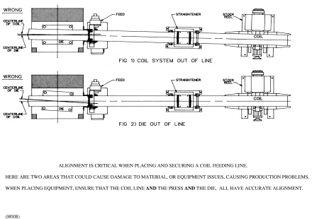
Proper alignment from press to feed rolls, to straightener to de-reeler keeps material feeding straight.
Use the lowest speed possible to accomplish proper feeding relative to press Strokes per Minute (SPM)
Prevent damage to drive components by not hitting mechanical stops.
Keeping the air PSI sufficient to prevent material slippage but not too excessive.
Too much air PSI will put excess strain on equipment and your compressed air system.
Minimize jerking and slapping of material with proper speed adjustments on payout equipment to achieve optimum and appropriate speed.
Know -your press cycle, when punches and pilots open and close, feed lengths, ram heights, pass line height, etc.
Keeping electrical connections properly routed to avoid unwanted "AC Noise" on the Inputs or Output of the control
Inspection
Occasional cleaning of metal dust and debris, cooling fans, and filters
Paying attention to loose bolts, brass shavings, or missing pieces
Maintain a proper file of technical data and prints per machine
Proper alignment from press to feed rolls, to straightener to de-reeler keeps material feeding straight and will not overwork your motor.
Check that electrical connections are tight, vibrations can occasionally shake them loose
Keeping air PSI to cylinders, pinch rolls and de-reeler brakes properly set
Using edge guides properly and not squeezing the edge of your material too tightly
Not running material into mechanical stops
Proper alignment of feed rolls to press tooling
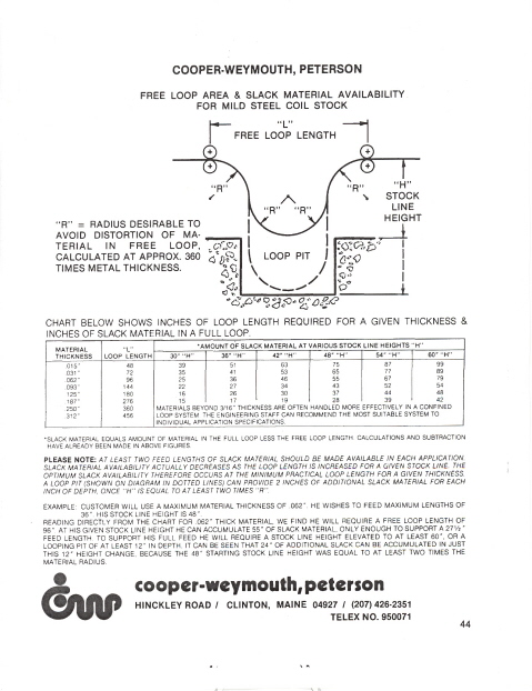
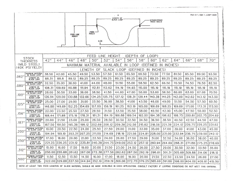
Having the correct slack loop length
Listening to operators who are familiar with operating the equipment on a regular basis. Although their questions or "funny noise" complaints seem bothersome- they may save you costly maintenance repairs.
Performing "Scribe Test" or accuracy test of feed length and feed roll revolution as follows:
Calculate the circumference as (Roll Diameter x 3.1416 ) and enter this number as a feed length. Now scribe two lines-one in the lower roll and one matching line in the side plate. The purpose is to have these marks line up after each revolution of the feed rolls.
The circumference (= roll diameter x 3.1416 ) entered as a feed length will allow you to test the accuracy of the feeder.
Lubrication
Check Filter, Regulators and Lube bowls (F.R.L.'s) to maintain oil levels and remove water daily.
Gear teeth should be greased or coated with "Never Seize" or after 1000 operating hours.
Chains, sprockets and couplings should be inspected and lubed with general purpose grease, such as Mobil EP, 1 monthly.
Mandrel expansion wedges
and linkage on stock reels should be greased monthly.
Lube screw shafts and edge guide bushings with a light oil monthly.
Lube feed roll assembly weekly. Remove covers to expose grease fittings.
Maintain proper lube levels in gearboxes, oil bowls, and Trabon canisters. Grease dispensers (GenPurpose grease- EP1)
Pneumatic oil bowls (light oil - #10) and Hydraulic pumps (Mobil DTE 24 or equiv).
With an automatic Trabon Lubrication system
option: Adjust the timer control to assure proper greasing
intervals. Refer to the literature provided with your Trabon Auto
Lube System. The canister should be filled with general-purpose
grease when it is empty. Should any of the lines get plugged, the canister has a pressure relief disc that will rupture and allow grease to spill out. When this happens, there is probably a line plugged or a manifold plugged. Replace the disc and check where grease is not being received and remove any blockage or replace any pinched lube line. Also you can remove the lube system fitting and use a single grease fitting at the suspected component. This way you can determine if the problem is the component or in the lube line. There are a few manual grease fittings in some places where it is not possible to use automatic lubrication. These should be included in a monthly PM program and serviced at sensible intervals.
Checking Your Feed Accuracy
Accuracy problems can be caused by different factors; or a combination of factors. If you are having accuracy problems with your servo feed, you should check the following.
1. Check the die to see if the proper feed length is set.
2. Also, binding of material can cause accuracy problems. Ensure that there is not any material binding in the die, at the edge guides or anywhere along the complete feed line. Also see "Feed Roll Slippage"
3. Roll Lift timing could cause inaccurate part lengths. Make sure that the roll lift is not occurring too early, or too late. (Note: Roll lifting is not always possible with dies that don't have pilot pins.) On cut-to-length systems, however, it is beneficial to release the rolls whenever possible.
4. Certain Materials can cause inaccuracies with part lengths. Sometimes pre-finished, pre-painted and galvanized materials have a tendency to slip on the rolls. This is sometimes very difficult to correct. Please consult with the factory if the problems persist.
Once you have checked and corrected any of the items listed above, run production and recheck the part to see if the accuracy problem has been corrected. If the part length is still not accurate you can then check the accuracy of the feeder using the following "Scribe Test Procedure"
1. Remove all material from the feeder.
2. Enter the 'circumference' of the roll as the part length.
| Model: |
Feed Length: |
| SMT4 or SMLT |
6.283" (Diameter X 3.1416) |
| SM |
6.283" |
| SMX |
8.639" |
| SMXH |
12.566" |
| SMXH6 |
18.849" |
For other models please consult the factory.
3. Remove the guard and scribe the bottom roll and the feed body directly in line with the scribe mark on the roll.
4. Set the feeder to speed 2.
5. Initiate the feeder for one feed length. The roll should make one revolution and return to its original position, with the two scribe marks in line with each other. Note: If you cycle the feeder numerous times and see a visible distance between the two scribe marks you must divide the distance by the number of strokes to get the correct accuracy.
If the feeder passes the scribe test you need to go back to items 1 thru 4 at the top of the page. If the feeder fails the scribe test you should check for loose gears on the motor shaft or lower roll, loose encoder connector, or possible faulty encoder.
FEED ROLL SLIPPAGE
One of the most common misconceptions that the roll feed is not accurate is because of the appearance of short parts; therefore, we assume there is something wrong with the feeder. Most of the time the problem lies with the material or the application.
Feed roll slippage happens for a number of reasons: guiding, die alignment, equipment alignment, material alignment, material weight, improper straightening procedures or improper application. Additionally, the material itself can be a factor: camber, crown, scalloped edges, oil can effect, etc. When guides are too tight, or the tooling is not aligned properly, there is additional stress between the material and the feed rolls. If this resistance is great enough, the rolls can slip, resulting in a short part. All of these issues are contributing factors to the causes of roll slippage.
Even under the best conditions, feed roll slippage is a fact of life. But, once you address the mechanical and material issues, thus reducing resistance, the slippage is minimized.
Any discrepancies left in part lengths should be addressed by compensating at the feed control. Most customers find this to be the best way to adjust for proper part length, in the case of servo-feeds. These adjustments can be through trial and error, or more often, by creating a formula that allows for a certain amount to be added depending on the part length. For example: the adjustment may be addressed by adding .001 of an inch per 3 inches of feed length.
By keeping all of these issues and
suggestions in mind, this should minimize slippage, resulting in the best and most accurate part possible. Always consult the service department if in doubt.
Servo Feed Drive Fault Causes
If you are getting the error,"Drive Fault", please use the following checklist to help get the problem resolved.
Testing a "Dry Run"
Test your motor by removing the stock from the feeder to simulate a "Dry Run".
Now
that your
stock material is out of the feeder, you should be able to power up and cycle your press while the feeder is in the Automatic mode. This will let you cycle your feed rolls to test your motor, amp and motor cables. Use this "Dry Run" to cycle around 100 times. If you can cycle the "Dry Run" without any trouble or error codes, then the motor, amp and motor cables are usually not the problem. If you have any trouble with the "Dry Run", double check your cables and connections making sure they are tight. You should also test your motor cables with an Ohm-meter to be sure there are no broken or shorted wires causing the problem. If you can't successfully operate the "Dry Run", you may need a new motor, amp or cable. Consult Factory.
Mechanical Binding?
Is there any excessive drag from gearing, tight edge guides, misalignment, stop blocks or timing conflicts?
Tight gearing? - check this by doing the following:
-turn
the power off and lock out, make sure the material is out of the feeder.
-remove the guards to expose the motor gears and turn them over by hand several revolutions.
The gears should turn over freely without any tight spots. If there are tight spots, the gears may be damaged or need readjusting-contact the factory for instructions.
Are you using stop blocks? This causes the
material to jam into a stop block and this stresses the motor and amp. Stop blocks were required on older less accurate air feeders but the servo-controlled feeders use an encoder to produce consistent accuracy thus eliminating the need for stop blocks. However, some customers have installed feed detection devices in place of Stop blocks.
Is your alignment from Feeder to Die-Set square within 1/32 of an inch? Proper alignment from press to feed rolls keeps material feeding straight and prevents extra undue stress on the motor and amp. If the die is crooked or the punches are dull, there will be extra drag on the material and this can cause drive faults.
Is the feed initiate and pilot release timing set properly? (Refer to the Timing Example Diagram)
It is very important to know the position of your press stroke and tooling.
This can be found by inching the press over slowly and watching the tooling or using a feeler piece of stock to accurately know when your tool opens and closes. If you have a PLS read out, this will be very helpful and the settings should be noted and used as a reference.
If you do not have a PLS readout, you can still adjust your feeding signal and pilot release device switch by watching the tooling or using a feeler piece of stock and inching your press around. Your feed initiate signal should happen as soon as the tool opens and the punches and pilots clear as the press cycles up towards top. The feeding needs to be done before the tool closes again on the down cycle. You should try to use the lowest speed possible to accomplish the best feeding results relative to press Strokes per Minute (SPM) of your press.
Cables, connections and power:
Check that all wiring is:
-routed away from other AC voltage sources
-properly shielded and grounded, especially I/O wires such as feed initiate or E-stops.
-tightly connected at the motor end and at the control terminal boards.
-connected to "clean" power circuits that are not in line with welders or other high inductance loads.
-test your motor cables with an Ohm-meter to be sure there are no broken or shorted wires.
Use surge filters on incoming power feeds whenever possible to prevent AC noise and spike problems.
Measure your incoming voltage at the Servo-Amplifier to be sure it is correct for the voltage specification of your system.
Electrical Noise and Power Spike Issues
The servo control amplifiers are the brains of the equipment, so the following factors need to be considered when wiring up the equipment.
Power spikes in the AC feed lines from lightning, motors starting, unbalanced loads or etc. will generate noise, which can travel via the DC common and AC ground connection and corrupt personality modules or other sensitive electronic components. This AC "noise" will cause many problems, so it's best to eliminate this noise by wiring into "clean" power circuits, using suppressors, shielded wires and grounding the shields of any wires that attach to the inputs/outputs (I/O) of the control amplifier. The feed initiate input wire, for example, should be a shielded cable and should not be routed near AC wiring.
I/O signals wired into the control amplifier need to be free of AC noise.
Wires for I/O should not be in the same conduit as AC power wires.
Wires for I/O connected to the amplifier control should be shielded and the shield needs to be connected to a good clean ground reference source.
Check for loose connections at the main power lugs to be sure all terminations are tight.
An oscilloscope can be used to find AC noise or spikes on power and control circuits.
High inductive loads, such as large motors or welding equipment, should not be on the same circuit that supplies power to the control amplifiers.
Any relays that are connected to the I/O of the control amplifier must have a suppressor diode across their coil. This prevents any voltage from being induced back into the control amplifier.
IQ2000 Servo Feed Control Diagnostics & Troubleshooting
This Servo-Amplifier is one of many
different type of controllers we use. The following should only be
used to trouble shoot the IQ2000 control. This is the "brain and muscle" of your servo feeder. They are very durable and will display error codes if trouble is present which allows the user to correct any problems before catastrophic failure occurs. Some common error codes and suggested resolutions are listed below.
These amplifiers have a removable Personality Eprom which stores the software needed to control the servo-motor. The Personality Eprom should only need to be replaced if the machine characteristics have changed, the motor model has changed, or the Eprom Chip has been damaged by AC noise or electrical spikes. Please refer to the technical note titled, "Preventing Spikes".
Some faults can be reset by powering off the control disconnect handle and waiting for a minute before turning it back on.
The first level of diagnostics is the LED on the front of the Servo-Amplifier.
Green = No Fault Status
Red = Fault Status
Off = No Power
E 16 = Invalid Op Code
The control tried to execute a program that is not valid or is corrupted.
E 33 = I AVG Fault
The average current output has exceeded safe levels for the motor and amplifier. This can be caused by material drag, excessive duty cycle, mechanical binding in the gears of the feed body, shorted motor cables or
Problems with the incoming AC power on L1 and L2.
E 34 = Excessive FE
The encoder has sensed a Following Error that exceeds the limits of preset parameters. Check for faulty connections at the encoder cable or test the encoder cable for breaks or shorts. This could also be caused by a bad encoder which is mounted inside the motor and requires replacing the motor if all other cables prove good. Sometimes a sudden mechanical bind or hitting a positive stop will cause this fault and an I Average fault.
E 35 = Excessive Speed
The commanded velocity of a move exceeded the preset limits of the Overspeed value. Check cables and mechanical binding as well as program data entered in the job. Try running a different job number.
E 40 = Motor Overtemp
The temperature sensor in the motor has sensed unsafe levels. Check for excessive material drag and mechanical binding. Test the cables for tightness or shorts. If this fault goes away by removing just the 4 pin connector from the motor, the cable is good and the problem is due to binding or a worn out motor.
E 41 = Power Module Fault
This is caused by excessive current inside the amplifier. See E40 above for possible resolutions.
E 42 = Bus Under Voltage
This indicates a problem with the internal DC voltage supply. Check the incoming power and any fuses that are in the system.
Diagnostics and Troubleshooting for IQ 2000 Servo Feed Controls
E 43 = Peak Over current
Similar to E 33. This means that the amplifier detected a short circuit in the motor or the motor cables are shorted.
E 47 = Watchdog Test Fault
The watchdog test failed. This is caused by AC Noise or Spikes corrupting the Eprom. This could require replacing the Eprom Personality Module
E 48 = Personality Fault
Similar to E47 Above. Requires replacing the Eprom
E 49 = Watchdog Reset
Similar to E48 and E47 above. Requires replacing the Eprom
E 44 = Bus Over Voltage
The amplifier detected unsafe voltage levels and could be related to the incoming power or the shunt fuse.
E 51 = Eprom Checksum
Checksum test has failed. Replace the Eprom
E 54 = Parameter Checksum
Similar to E51 above.
E 70 = Illegal Pgm Number
An invalid program was entered. The Eprom could be corrupted and needs to be replaced. Try entering a different job number or turning the power off for a while and then back on.
Error codes are from the Reliance IQ2000 Manual.
Servomax Servo Feed Speed Calculator
You can predict the speed of Servo Max II machines through the keypad on the machine.
Step through the program as follows:
1. Program a job as normal filling in the following fields: Job Number, Feed Length, Speed, and Batch Count
2. When at the end of the program and the control asks change yes or no? Reply No.
3. With the cursor in the Job Field enter 65 for SMXII Models, for SMXIII and SMXSE Models enter 15765 in the feed length field.
4. The screen will ask 180 degrees of press cycle?
5. Place the cursor in the Field of 180 the correct amount of degrees of press cycle. Then enter.
6. The program will respond with strokes per minute. The press can safely run.
This subroutine will analyze the job you exited from.
You can vary the speed (1-10) in that field and best match your press speed, in SPM.
You can run this subroutine on all user jobs.
Run the feeder at the slowest speed possible and still maintain you press SPM. This reduces wear on the feeder.
Capacity
| Model |
(Full Width) |
|
(Half Width) |
|
SMX06 |
0.187 |
|
0.187 |
|
SMX12 |
0.156 |
|
0.187 |
|
SMX18 |
0.125 |
|
0.170 |
|
SMX24 |
0.093 |
|
0.140 |
|
SMX30 |
0.078 |
|
0.125 |
|
SMX12H |
0.250 |
|
0.281 |
|
SMX18H |
0.187 |
|
0.250 |
|
SMX24H |
0.187 |
|
0.250 |
|
SMX30H |
0.156 |
|
0.219 |
|
SMX36H |
0.125 |
|
0.187 |
|
SMX42H |
0.093 |
|
0.156 |
|
The following models have a fixed Maximum thickness regardless of material width.
|
SMX48H |
0.062 |
|
|
|
SMX12H6 |
0.328 |
|
|
|
SMX18H6 |
0.328 |
|
|
|
SMX24H6 |
0.281 |
|
|
|
SMX30H6 |
0.250 |
|
|
|
SMX36H6 |
0.203 |
|
|
|
SMX42H6 |
0.156 |
|
|
|
SMX48H6 |
0.125 |
|
|
|
SMX54H6 |
0.110 |
|
|
|
SMX60H6 |
0.093 |
|
|
|
SM06 |
0.125 |
|
|
|
SM12 |
0.078 |
|
|
|
SMT4 |
0.062 |
|
|
|
SMLT |
0.062 |
|
|
|
|
|
|
|
|
Slack Loop Chart